Building the Front End: My FSAE Chassis Experience
What It Actually Takes to Design an FSAE Chassis
Formula SAE is not your typical class project. When I joined the chassis subteam, I walked into a world where every tube, every joint, and every diagonal brace had to earn its place, both structurally and by the rulebook. The rules are unforgiving: miss a clause, and your design could be disqualified before a single lap is run.
My role spanned two overlapping tracks. On the design side, I contributed to the SolidWorks chassis model, working from rough 2D sketches through iterative 3D revisions until landing on a final layout. On the research side, I dug into a specific question the team was wrestling with: can we remove the front bulkhead diagonal brace, and under what conditions?
The Diagonal Brace Question
Rule F.8.4.3 presented a real fork in the road. If the front bulkhead (FBH) exceeds 400 mm by 350 mm, or if the team is running a standard honeycomb impact attenuator, one of two conditions has to be satisfied: include a diagonal or X-brace in the FBH, or prove through physical testing that the anti-intrusion plate (AIP) does not permanently deflect more than 25 mm.
F.8.4.3: If the outside profile of the FBH is more than 400 mm by 350 mm, or uses a standard honeycomb IA, then either the FBH must include a diagonal or X-brace, or the AIP must not permanently deflect more than 25 mm from physical testing per F.8.8.6 and F.8.8.7.
That second path, testing in lieu of the brace, opened up meaningful design flexibility. Since building your own dynamic test apparatus is explicitly prohibited, quasi-static testing on a university hydraulic press is the most accessible route. Texas A&M's Automated Fabrication and Design Lab has the equipment to run it.
The AIP itself carries its own material requirements: at minimum 1.5 mm solid steel or 4.0 mm solid aluminum, with a profile that aligns with or exceeds the outer dimensions of the FBH tubes on all sides. A composite AIP (CAIP) must survive a 120 kN distributed load without failure, and that has to be verified against a test fixture that honestly represents the front 50 mm of the chassis, not a solid block standing in for it.
The diagonal brace exists to prevent the front bulkhead from folding under off-axis loads. Remove it, and your AIP has to prove it can hold the line instead, not just on paper, but on a hydraulic press.
From 2D Sketch to Final SolidWorks Model
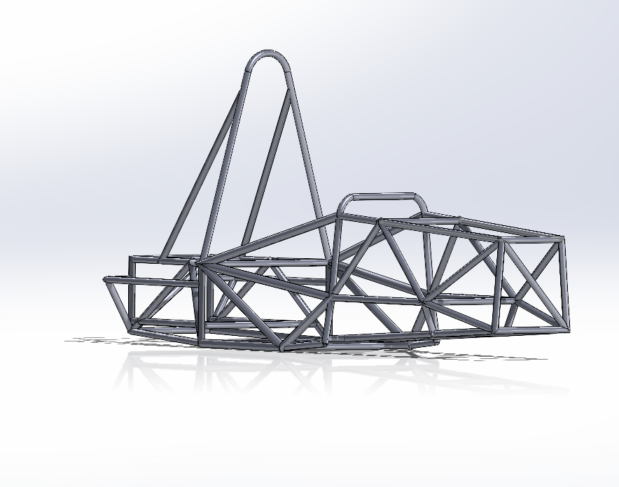
The chassis evolved through a natural but demanding progression. What started as rough proportional geometry on paper became a fully parametric 3D weldment model with real suspension pickup points, real powertrain packaging constraints, and real driver template checks.
Weeks 1-2: Rulebook Study and Material Selection
Parsed FSAE structural rules and cross-referenced tube sizing requirements. Built a weighted decision matrix across four candidate steel alloys, evaluating strength, price, and machinability.
Weeks 3-4: Initial 2D and 3D Sketch
Translated rough proportions into a SolidWorks weldment layout. The first 3D pass was intentionally over-braced because it's easier to figure out what to remove once you can see the full geometry.
Weeks 5-9: Iteration and Cross-Team Coordination
Major redesign cycle to resolve internal sizing, correct suspension pickup geometry, and coordinate with powertrain. The main hoop angle was reduced, the side impact member was refined, and a shoulder bar was added.
Weeks 10-12: Block Integration and Simulation Setup
Added volumetric placeholder blocks for the body, leg compartment, and engine to verify spatial packaging. Started setting up Tier 2 FEA simulations to validate structural rigidity before tube selection was locked in.
Why We Chose AISI 1020
Four alloy steels were evaluated against a weighted decision matrix. The criteria were strength, cost, and machinability, each carrying different multipliers based on what actually matters for a student-built race chassis on a finite budget.
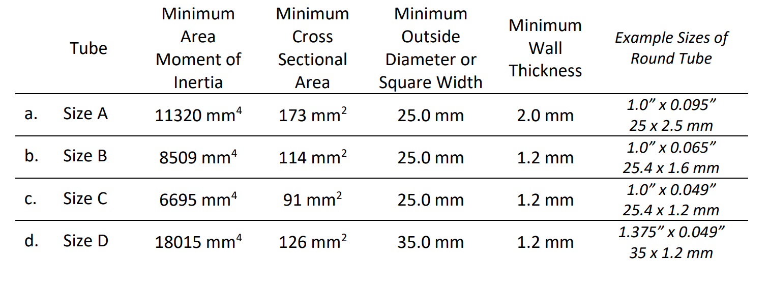
AISI 1020 won on availability and machinability, two things that matter enormously when you're fabricating in a university shop with limited machine time. Its yield strength of 351 MPa and Young's modulus of 200 GPa gave us sufficient margin for anticipated loads. The tube stock came in three wall thicknesses: 1.0 inch by 0.095 inch, 1.0 inch by 0.065 inch, and 1.375 inch by 0.049 inch, allowing us to tune section properties across different zones of the chassis without switching alloys.
With the full weldment modeled, the chassis came in at approximately 122.6 lbs, a baseline we will be working to optimize once FEA results come back.
What FSAE Teaches You That Coursework Does Not
There is a particular kind of engineering problem-solving that only appears in competition projects. Textbooks give you bounded, well-defined scenarios. FSAE throws you into a space where the rules constrain your design, your budget constrains your material, your teammates' work constrains your geometry, and your timeline constrains everything else simultaneously.
The diagonal brace research forced me to actually read a technical rulebook, not skim it, but trace through cross-references from F.8.4.3 to F.8.8.6 to F.8.8.7 to F.8.7.4, building a complete picture of what compliance actually means. That kind of systematic technical reading is a skill I did not realize I was developing until I had to do it under real pressure.
The SolidWorks work taught a different lesson: first designs are always wrong, and that is fine. The initial model had internal sizing issues, misplaced suspension points, and main hoop geometry that failed the driver template. Every one of those corrections made the final design sharper. Iteration is not failure; it is the process.
I am planning to push into FEA in the next phase and see how the numbers hold up against our structural intuition. More to come.